Wednesday, June 8, 2016

CN - Access Methods

Access Methods

In computing, an access method is a program or a hardware mechanism that moves data between the computer and an outlying device such as a hard disk (or other form of storage) or a display terminal.

It is sometimes used to refer to the mechanics of placing or locating specific data at a particular place on a storage medium and then writing the data or reading it. Access Method is also used to describe the way that data is located within a larger unit of data such as a data set or file.

Types of Access Methods

  1. Ethernet
    • CSMA/CD
    • Switched Ethernet
    • Ethernet Frame
    • PoE (Power over Ethernet)
  2. Token Ring
  3. FDDI
  4. ATM

Ethernet - CSMA/CD

In CSMA/CD (Carrier Sense Multiple Access/Collision Detection) Access Method, every host has equal access to the wire and can place data on the wire when the wire is free from traffic. When a host want to place data on the wire, it will “sense” the wire to find whether there is a signal already on the wire. If there is traffic already in the medium, the host will wait and if there is no traffic, it will place the data in the medium. But, if two systems place data on the medium at the same instance, they will collide with each other, destroying the data. If the data is destroyed during transmission, the data will need to be re-transmitted. After collision, each host will wait for a small interval of time and again the data will be re-transmitted, to avoid collision again.

CSMA/CD Events


Switched Ethernet

An Ethernet LAN that uses switches to connect individual hosts or segments. In the case of individual hosts, the switch replaces the repeater and effectively gives the device full 10 Mbps bandwidth (or 100 Mbps for Fast Ethernet) to the rest of the network. This type of network is sometimes called a desktop switched Ethernet. In the case of segments, the hub is replaced with a switching hub.


Ethernet Frame

 • A Ethernet Frame is a physical layer communications transmission, comprised of 6 fields which are assembled to transmit any higher layer protocol over an Ethernet fabric. 

An Ethernet frame is preceded by a preamble and start frame delimiter (SFD), which are both part of the Ethernet packet at the physical layer. Each Ethernet frame starts with an Ethernet header, which contains destination and source MAC addresses as its first two fields. The middle section of the frame is payload data including any headers for other protocols (for example, Internet Protocol) carried in the frame. The frame ends with a frame check sequence (FCS), which is a 32-bit cyclic redundancy check used to detect any in-transit corruption of data.

• A IP Packet is a formatted unit of data which can be transmitted across numerous physical topologies including Ethernet, Serial, SONET and ATM. 
• The important thing to understand is that a frame always refers to the physical medium.


PoE (Power over Ethernet) 

What is Power over Ethernet?

Power over Ethernet (POE) is a technology that lets network cables carry electrical power.

For example, a digital security camera normally requires two connections to be made when it is installed:
network connection, in order to be able to communicate with video recording and display equipment

power connection, to deliver the electrical power the camera needs to operate

However, if the camera is POE-enabled, only the network connection needs to be made, as it will receive its electrical power from this cable as well.
Power over Ethernet reduces the number of cables required to connect a POE IP camera
Why use POE?

Specifying Power over Ethernet brings many advantages to an installation:
Time and cost savings - by reducing the time and expense of having electrical power cabling installed.  Network cables do not require a qualified electrician to fit them, and can be located anywhere.

Flexibility - without being tethered to an electrical outlet, devices such as IP cameras and wireless access points can be located wherever they are needed most, and repositioned easily if required.

Safety - POE delivery is intelligent, and designed to protect network equipment from overload, underpowering, or incorrect installation.

Reliability - POE power comes from a central and universally compatible source, rather than a collection of distributed wall adapters.  It can be backed-up by an uninterruptible power supply, or controlled to easily disable or reset devices.

Scalability - having power available on the network means that installation and distribution of network connections is simple and effective.

Token Ring

Token ring or IEEE 802.5 is a network where all computers are connected in a circular fashion. The term token is used to describe a segment of information that is sent through that circle; when a computer on the network can decode that token, it receives data. The token ring is used by ARCNET, token bus and FDDI. Today, 802.5 and Token ring are considered inactive.

The token ring LAN process is delineated by the following sequence of events:
  • A token continually circulates inside the toke ring LAN
  • To transmit a message, a node inserts a message and destination address inside an empty token.
  • The token is examined by each successive node. 
  • The destination node copies the message data and returns the token to the source with the source address and a data receipt message.
  • The source receives the returned token, verifies copied and received data and empties the token.
  • The empty token now changes to circulation mode, and the process continues.

FDDI

FDDI (Fiber Distributed Data Interface) is a set of ANSI and ISO standards for data transmission on fiber optic lines in a local area network (LAN) that can extend in range up to 200 km (124 miles). The FDDI protocol is based on the token ring protocol.

Advantages
  • provides high-speed network backbones that can be used to connect and extend LANs.
  • has error-detection and correction capabilities.
  • Fiber-optic cable such as the cable used with Fiber Distributed Data Interface (FDDI) can support very large volumes of data over large distances.
Disadvantage:
  • expensive technology to set up because the network devices require a special network card and also fiber-optic cabling is required

ATM

ATM is a connection-oriented, unreliable (does not acknowledge the receipt of cells sent), virtual circuit packet switching technology. Unlike most connectionless networking protocols, ATM is a deterministic networking system — it provides predictable, guaranteed quality of service. From end to end, every component in an ATM network provides a high level of control. ATM technology includes:
  • Scalable performance. ATM can send data across a network quickly and accurately, regardless of the size of the network. ATM works well on both very low and very high-speed media.
  • Flexible, guaranteed Quality of Service (QoS). ATM allows the accuracy and speed of data transfer to be specified by the client. This feature distinguishes ATM from other high-speed LAN technologies such as gigabit Ethernet. The QoS feature of ATM also supports time dependent (or isochronous) traffic. Traffic management at the hardware level ensures that quality service exists end-to-end. Each virtual circuit in an ATM network is unaffected by traffic on other virtual circuits. Small packet size and a simple header structure ensure that switching is done quickly and that delays due to high traffic are minimized.
  • Unobstructed speed. ATM imposes no architectural speed limitations. Its pre-negotiated virtual circuits, fixed-length cells, message segmentation and re-assembly in hardware, and hardware-level switching all help support extremely fast forwarding of data.
  • Integration of different traffic types. ATM supports integration of voice, video, and data services on a single network. ATM over Asymmetric Digital Subscriber Line (ADSL) enables residential access to these services.

Connection Types: LAN vs. ATM


Traditional LANs, such as Ethernet and Token Ring, use a connectionless, unreliable approach, that cannot guarantee successful transmission when sending information across the network. Likewise, TCP/IP data transfers between networks are connectionless and unreliable. ATM, which is a connection-oriented, circuit-based technology, differs from the traditional approaches to networking.
Further research here


Referrence:

Tuesday, June 7, 2016

INSERT
Tbl_lecturer
INSERT INTO `tbl_lecturer`(`lecturer_id`, `lecturer_name`, `course_id`) VALUES ('','Jenelyn','1');
INSERT INTO `tbl_lecturer`(`lecturer_id`, `lecturer_name`, `course_id`) VALUES ('','Dawn','2');
INSERT INTO `tbl_lecturer`(`lecturer_id`, `lecturer_name`, `course_id`) VALUES ('','Mareden','3');
INSERT INTO `tbl_lecturer`(`lecturer_id`, `lecturer_name`, `course_id`) VALUES ('','Lorenzo','4');
INSERT INTO `tbl_lecturer`(`lecturer_id`, `lecturer_name`, `course_id`) VALUES ('','Maya','5');
Results:
Tbl_course
INSERT INTO `tbl_course`(`course_id`, `course_name`) VALUES ('','HND');
INSERT INTO `tbl_course`(`course_id`, `course_name`) VALUES ('','DIT');
INSERT INTO `tbl_course`(`course_id`, `course_name`) VALUES ('','L4DC');
INSERT INTO `tbl_course`(`course_id`, `course_name`) VALUES ('','L5DC');
INSERT INTO `tbl_course`(`course_id`, `course_name`) VALUES ('','L3DC');

Results:


Tbl_course
INSERT INTO `tbl_studentinfo`(`std_id`, `std_name`, `std_address`, `std_contact`, `std_age`, `std_gender`, `course_id`) VALUES ('','Jim','St. George Strt.','8908900','12','Male','1');
INSERT INTO `tbl_studentinfo`(`std_id`, `std_name`, `std_address`, `std_contact`, `std_age`, `std_gender`, `course_id`) VALUES ('','Jim','St. Suleiman Rd.','8918911','21','Male','2');
INSERT INTO `tbl_studentinfo`(`std_id`, `std_name`, `std_address`, `std_contact`, `std_age`, `std_gender`, `course_id`) VALUES ('','Tim','Jerudong Road Lot 2','8768761','14','Male','3');
INSERT INTO `tbl_studentinfo`(`std_id`, `std_name`, `std_address`, `std_contact`, `std_age`, `std_gender`, `course_id`) VALUES ('','Karena','Malayan Strt.','8128122','20','Female','4');
INSERT INTO `tbl_studentinfo`(`std_id`, `std_name`, `std_address`, `std_contact`, `std_age`, `std_gender`, `course_id`) VALUES ('','Jennipher','Malayan Strt','8908912','21','Female','5');
Results:


SELECT QUERY
1.    Retrieve all data of the students.
SELECT `std_id`, `std_name`, `std_address`, `std_contact`, `std_age`, `std_gender`, `course_id` FROM `tbl_studentinfo`;
2.    Retrieve all data of different courses
SELECT `course_id`, `course_name` FROM `tbl_course`;


3.    Retrieve only the name and contact of all students.
SELECT `std_name`, `std_contact`  FROM `tbl_studentinfo`;


4.    Retrieve all teacher’s names and student’s names.
SELECT `tbl_studentinfo`.`std_name`, `tbl_lecturer`.`lecturer_name` FROM
`tbl_lecturer`, `tbl_studentinfo`;


5.    Retrieve all teacher’s names and student names with the same course.
SELECT `tbl_studentinfo`.`std_name`, `tbl_lecturer`.`lecturer_name` FROM
`tbl_lecturer`, `tbl_studentinfo`
where `tbl_studentinfo`.`course_id` = `tbl_lecturer`.`course_id`;


6.    Retrieve student’s name and course’s names with the course ID.
SELECT `tbl_studentinfo`.`std_name`, `tbl_course`.`course_name` FROM
 `tbl_studentinfo`, `tbl_course`
where `tbl_studentinfo`.`course_id` = `tbl_course`.`course_id`;
7.    Retrieve unique values in student table
SELECT DISTINCT `std_name` FROM `tbl_studentinfo`;


8.    Retrieve student’s name and age with the age with less than 21.
SELECT `std_name`, `std_age` FROM `tbl_studentinfo` WHERE `std_age`< '21';
9.    Retrieve student’s name with the age less than 25 and the gender is male
SELECT `std_name`, `std_age` FROM `tbl_studentinfo` WHERE `std_age`< '25'
AND `std_gender` = 'male';
10. Retrieve all lecturer’s name which has the letter ‘n’
SELECT * FROM `tbl_lecturer` WHERE `lecturer_name` LIKE '%j%'


11. Sorting Student table by age
SELECT * FROM `tbl_studentinfo` ORDER BY `std_age`;
12. Sorting Student table by name ASCENDING order
SELECT * FROM `tbl_studentinfo` ORDER BY `tbl_studentinfo`.`std_name` ASC
13. Sorting student table by7 name in Descending order
SELECT * FROM `tbl_studentinfo` ORDER BY `tbl_studentinfo`.`std_name` DESC


14. Retrieve lecturer’s name LIMIT by three (only shows first three in the table).
SELECT `lecturer_name` FROM `tbl_lecturer` LIMIT 3;
15. Retrieve Student’s name LIMIT by three (only shows first three name in table).
SELECT `std_name` FROM `tbl_studentinfo` LIMIT 3;
16. Retrieve Student’s name LIMIT by three IN ASCENDING order
SELECT `std_name` FROM `tbl_studentinfo`ORDER by `tbl_studentinfo`.`std_name` ASC LIMIT 3;


17. Update student table SET a student name to ANY name
UPDATE `tbl_studentinfo` SET `std_name` = 'jOHNNY'
WHERE `STD_ID` = '1';


18. Update COURSE HND into HND in Computing
UPDATE `tbl_course` SET `course_name` = 'HND in Computing'
WHERE `course_name` = 'HND';
19. Delete A COURSE
DELETE FROM `tbl_course` WHERE `course_id` = '1';

Sunday, June 5, 2016

CN - Hybrid Topologies & Backbone Networks

Hybrid Topology

Definition: hybrid topology is a type of network topology that uses two or more other network topologies, including bus topologymesh topologyring topologystar topology, and tree topology.

A hybrid topology is always produced when two different basic network topologies are connected. Two common examples for Hybrid network are: star ring network and star bus network. 


Advantages and Disadvantages

Adv:
  •  Reliable : Unlike other networks, fault detection and troubleshooting is easy in this type of topology. The part in which fault is detected can be isolated from the rest of network and required corrective measures can be taken, WITHOUT affecting the functioning of rest of the network.
  • Scalable: Its easy to increase the size of network by adding new components, without disturbing existing architecture.
  • Flexible: Hybrid Network can be designed according to the requirements of the organization and by optimizing the available resources. Special care can be given to nodes where traffic is high as well as where chances of fault are high. 
  •  Effective: Hybrid topology is the combination of two or more topologies, so we can design it in such a way that strengths of constituent topologies are maximized while there weaknesses are neutralized. For example we saw Ring Topology has good data reliability (achieved by use of tokens) and Star topology has high tolerance capability (as each node is not directly connected to other but through central device), so these two can be used effectively in hybrid star-ring topology. 
Disadv:
  • Complexity of Design: One of the biggest drawback of hybrid topology is its design. Its not easy to design this type of architecture and its a tough job for designers. Configuration and installation process needs to be very efficient.
  • Costly Hub: The hubs used to connect two distinct networks, are very expensive. These hubs are different from usual hubs as they need to be intelligent enough to work with different architectures and should be function even if a part of network is down.
  • Costly Infrastructure: As hybrid architectures are usually larger in scale, they require a lot of cables, cooling systems, sophisticate network devices, etc.
Types

tree network, or star-bus network, is a hybrid network topology in which star networks are interconnected via bus networks.Tree networks are hierarchical, and each node can have an arbitrary number of child nodes.


star-ring network consists of two or more ring networks connected using a multi-station access unit (MAU) as a centralized hub.


A Snowflake topology is really a "Star of Stars" network, so it exhibits characteristics of a hybrid network topology but is not composed of two different basic network topologies being connected.


Backbone Networks

Backbone part of the network is a core of the network with its high throughput capability and significant bandwidth. It is made for the ability of network to communicate with external networks (like Internet). It is a root of the network tree, that has rest of the network growing from it. On a large scale, a backbone is a set of pathways to which other large networks connect for long distance communication.

A backbone may interconnect different LANs in offices, campuses or buildings. When several local area networks (LAN) are being interconnected over a considerable area, the result is a wide area network (WAN), or metropolitan area network (MAN) if it happens to serve the whole city.

Types

Serial Backbone

Serial backbone is formed of two or more devices that are connected in a daisy chain (linked series). It is a simplest kind of backbone. As can be seen from the figure below, serial backbone can be made not only from switches, but also from gateways and routers.
While designing the backbone, the one should consider the limit of the devices that can be connected to the backbone in the repeating fashion. Exceeding the limit would result in the unexpected errors and data loss in the network. Serial backbone networks are not very fault tolerant and not very scalable, that make them less commonly used than the distributed backbone.


Distributed Backbone

Distributed backbone uses hierarchical topology of the network, where a number of intermediate devices are connected to single or multiple connectivity devices. These central connectivity devices could be switches or routers, and shown with purple color in the figure shown below.

This type of backbone is easily scalable since new layers of devices can be added with no troubles. Distributed backbone allows simple administration and management of the network due to its segregation. This type of network can have daisy chain linked devices for the backbone, however, designer should consider the same limitations as for the serial backbone.


Simple Distributed Backbone

The next figure below provides a view of more complicated distributed backbone that connects multiple LANs together. LANs are interconnected with routers that form the backbone.


Complicated Distributed Backbone
To conclude, distributed backbone is cheap, easy, and quick to implement.

Parallel backbone

Parallel backbone is a variation of the collapsed backbone, where devices are having more than one connection between them. Shown in the figure below, there are multiple connections between the high level routers and the network segments. Duplicate connections ensure networks availability at anytime, higher speeds, and high fault tolerance. Logical drawback of this solutions is the increased price, since amount of required cabling is highly increased. It is not obligatory to have duplicate connections between all the devices, selective implementation of parallel structure would significantly lower the overall price and make additional ports of the devices available.

Parallel backbone network

Collapsed backbone

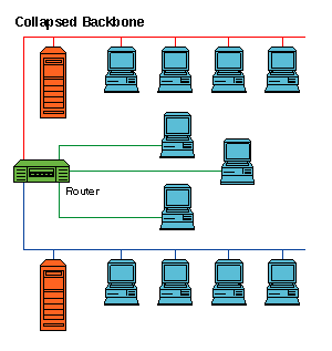
This type of backbone uses single, powerful router as the central connection point for multiple subnetworks. As the figure below shows, the central device is the highest level of the backbone. It should have powerful computational power in order to manage big traffic coming in. This is highly risky, since if the central device fails, the whole network would be down. However, this type of backbone is useful for the one who wants to interconnect two types of subnetworks, with ability to manage and troubleshoot them.
Collapsed backbone network

Switching

A network consists of many switching devices. In order to connect multiple devices, one solution could be to have a point to point connection in between pair of devices. But this increases the number of connection. The other solution could be to have a central device and connect every device to each other via the central device which is generally known as Star Topology. Both these methods are wasteful and impractical for very large network. The other topology also can not be used at this stage. Hence a better solution for this situation is SWITCHING. A switched network is made up of a series of interconnected nodes called switches. 

Types of Switching Techniques

There are basically three types of switching methods are made available. Out of three methods, circuit switching and packet switching are commonly used but the message switching has been opposed out in the general communication procedure but is still used in the networking application.
  1. Circuit Switching
  2. Packet Switching
  3. Message Switching


Circuit Switching

Circuit Switching is generally used in the public networks. It come into existence for handling voice traffic in addition to digital data. How ever digital data handling by the use of circuit switching methods are proved to be inefficient. The network for Circuit Switching is shown in figure.
An example of a circuit switched network is a telephone network.  The remote access link for each major node in the circuit associated with a phone call is established for the duration of the call.  It is also the case that the pathway taken might be different from one call to the next.


  • Here the network connection allows the electrical current and the associated voice with it to flow in between the two respective users. The end to end communication was established during the duration of call.
  • In circuit switching the routing decision is made when the path is set up across the given network. After the link has been sets in between the sender the receiver then the information is forwarded continuously over the provided link.

  • In Circuit Switching a dedicated link/path is established across the sender and the receiver which is maintained for the entire duration of conversation.

Packet Switching

Packet-switched networks move data in separate, small blocks -- packets -- based on the destination address in each packet. When received, packets are reassembled in the proper sequence to make up the message. Circuit-switched networks require dedicated point-to-point connections during calls.


Message Switching

  1.  A message is a logical unit of information and can be of any length.
  2. In message switching, if a station wishes to send a message to another station, it first adds the destination address to the message.
  3. Message switching does not establish a dedicated path between the two communicating devices i.e. no direct link is established between sender and receiver.
  4. Each message is treated as an independent unit.
  5. In message switching, each complete message is then transmitted from device to device through the internetwork i.e. message is transmitted from the source node to intermediate node.
  6. The actual path taken by the message to its destination is dynamic as the path is established as it travels along.
  7. When the message reaches a node, the channel on which it came is released for use by another message.


References: