Hybrid Topology
Definition: A hybrid topology is a type of network topology that uses two or more other network topologies, including bus topology, mesh topology, ring topology, star topology, and tree topology.
A hybrid topology is always produced when two different basic network topologies are connected. Two common examples for Hybrid network are: star ring network and star bus network.
Advantages and Disadvantages
Adv:
- Reliable : Unlike other networks, fault detection and troubleshooting is easy in this type of topology. The part in which fault is detected can be isolated from the rest of network and required corrective measures can be taken, WITHOUT affecting the functioning of rest of the network.
- Scalable: Its easy to increase the size of network by adding new components, without disturbing existing architecture.
- Flexible: Hybrid Network can be designed according to the requirements of the organization and by optimizing the available resources. Special care can be given to nodes where traffic is high as well as where chances of fault are high.
- Effective: Hybrid topology is the combination of two or more topologies, so we can design it in such a way that strengths of constituent topologies are maximized while there weaknesses are neutralized. For example we saw Ring Topology has good data reliability (achieved by use of tokens) and Star topology has high tolerance capability (as each node is not directly connected to other but through central device), so these two can be used effectively in hybrid star-ring topology.
Disadv:
- Complexity of Design: One of the biggest drawback of hybrid topology is its design. Its not easy to design this type of architecture and its a tough job for designers. Configuration and installation process needs to be very efficient.
- Costly Hub: The hubs used to connect two distinct networks, are very expensive. These hubs are different from usual hubs as they need to be intelligent enough to work with different architectures and should be function even if a part of network is down.
- Costly Infrastructure: As hybrid architectures are usually larger in scale, they require a lot of cables, cooling systems, sophisticate network devices, etc.
Types
A tree network, or star-bus network, is a hybrid network topology in which star networks are interconnected via bus networks.Tree networks are hierarchical, and each node can have an arbitrary number of child nodes.

A star-ring network consists of two or more ring networks connected using a multi-station access unit (MAU) as a centralized hub.

A Snowflake topology is really a "Star of Stars" network, so it exhibits characteristics of a hybrid network topology but is not composed of two different basic network topologies being connected.

Backbone Networks
Backbone part of the network is a core of the network with its high throughput capability and significant bandwidth. It is made for the ability of network to communicate with external networks (like Internet). It is a root of the network tree, that has rest of the network growing from it. On a large scale, a backbone is a set of pathways to which other large networks connect for long distance communication.
A backbone may interconnect different LANs in offices, campuses or buildings. When several local area networks (LAN) are being interconnected over a considerable area, the result is a wide area network (WAN), or metropolitan area network (MAN) if it happens to serve the whole city.
Types
Serial Backbone
Serial backbone is formed of two or more devices that are connected in a daisy chain (linked series). It is a simplest kind of backbone. As can be seen from the figure below, serial backbone can be made not only from switches, but also from gateways and routers.
While designing the backbone, the one should consider the limit of the devices that can be connected to the backbone in the repeating fashion. Exceeding the limit would result in the unexpected errors and data loss in the network. Serial backbone networks are not very fault tolerant and not very scalable, that make them less commonly used than the distributed backbone.

Distributed Backbone
Distributed backbone uses hierarchical topology of the network, where a number of intermediate devices are connected to single or multiple connectivity devices. These central connectivity devices could be switches or routers, and shown with purple color in the figure shown below.
This type of backbone is easily scalable since new layers of devices can be added with no troubles. Distributed backbone allows simple administration and management of the network due to its segregation. This type of network can have daisy chain linked devices for the backbone, however, designer should consider the same limitations as for the serial backbone.
 |
| Simple Distributed Backbone |
The next figure below provides a view of more complicated distributed backbone that connects multiple LANs together. LANs are interconnected with routers that form the backbone.
 |
| Complicated Distributed Backbone |
To conclude, distributed backbone is cheap, easy, and quick to implement.
Parallel backbone
Parallel backbone is a variation of the collapsed backbone, where devices are having more than one connection between them. Shown in the figure below, there are multiple connections between the high level routers and the network segments. Duplicate connections ensure networks availability at anytime, higher speeds, and high fault tolerance. Logical drawback of this solutions is the increased price, since amount of required cabling is highly increased. It is not obligatory to have duplicate connections between all the devices, selective implementation of parallel structure would significantly lower the overall price and make additional ports of the devices available.
 |
| Parallel backbone network |
Collapsed backbone
This type of backbone uses single, powerful router as the central connection point for multiple subnetworks. As the figure below shows, the central device is the highest level of the backbone. It should have powerful computational power in order to manage big traffic coming in. This is highly risky, since if the central device fails, the whole network would be down. However, this type of backbone is useful for the one who wants to interconnect two types of subnetworks, with ability to manage and troubleshoot them.
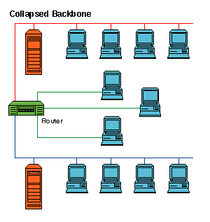 |
| Collapsed backbone network |
Switching
A network consists of many switching devices. In order to connect multiple devices, one solution could be to have a point to point connection in between pair of devices. But this increases the number of connection. The other solution could be to have a central device and connect every device to each other via the central device which is generally known as Star Topology. Both these methods are wasteful and impractical for very large network. The other topology also can not be used at this stage. Hence a better solution for this situation is SWITCHING. A switched network is made up of a series of interconnected nodes called switches.
Types of Switching Techniques
There are basically three types of switching methods are made available. Out of three methods, circuit switching and packet switching are commonly used but the message switching has been opposed out in the general communication procedure but is still used in the networking application.
- Circuit Switching
- Packet Switching
- Message Switching
Circuit Switching
Circuit Switching is generally used in the public networks. It come into existence for handling voice traffic in addition to digital data. How ever digital data handling by the use of circuit switching methods are proved to be inefficient. The network for Circuit Switching is shown in figure.
An example of a circuit switched network is a telephone network. The remote access link for each major node in the circuit associated with a phone call is established for the duration of the call. It is also the case that the pathway taken might be different from one call to the next.

- Here the network connection allows the electrical current and the associated voice with it to flow in between the two respective users. The end to end communication was established during the duration of call.
In circuit switching the routing decision is made when the path is set up across the given network. After the link has been sets in between the sender the receiver then the information is forwarded continuously over the provided link.
- In Circuit Switching a dedicated link/path is established across the sender and the receiver which is maintained for the entire duration of conversation.
Packet Switching
Packet-switched networks move data in separate, small blocks -- packets -- based on the destination address in each packet. When received, packets are reassembled in the proper sequence to make up the message. Circuit-switched networks require dedicated point-to-point connections during calls.

Message Switching
- A message is a logical unit of information and can be of any length.
- In message switching, if a station wishes to send a message to another station, it first adds the destination address to the message.
- Message switching does not establish a dedicated path between the two communicating devices i.e. no direct link is established between sender and receiver.
- Each message is treated as an independent unit.
- In message switching, each complete message is then transmitted from device to device through the internetwork i.e. message is transmitted from the source node to intermediate node.
- The actual path taken by the message to its destination is dynamic as the path is established as it travels along.
- When the message reaches a node, the channel on which it came is released for use by another message.

References:
- http://www.ianswer4u.com/2012/05/hybrid-topology-advantages-and.html#axzz4A5yyTQtP
- http://info-it.net/Basic-Network/hybrid-topology.php
- http://www.computerhope.com/jargon/h/hybrtopo.htm
- http://www.firewall.cx/networking-topics/general-networking/103-network-topologies.html
- http://www.orosk.com/NETWORKTOPOLOGIES/HYBRIDTOPOLOGY.htm
- http://fiberbit.com.tw/types-of-backbone-networks/
- http://blog.oureducation.in/types-of-switching/#!prettyPhoto