Wednesday, April 20, 2016

CN - Module 3- Network Media Types

Network Media Types

This post will explain about the four network media types:

  • Coaxial Cable
  • Twisted Pair
    • UTP& SDP
    • Straight-through, crossover & rollover cable
  • Fiebr-optic cable
  • Wireless Technologies
    • 802.11, 802.11b, 802.11g, 802.11n


Coaxial Cable

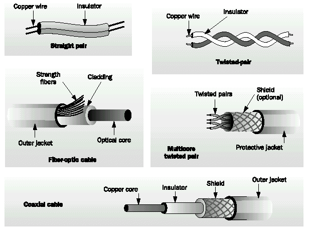
A solid-core copper wire runs down the middle of the cable. Around that solid-core copper wire is a layer of insulation, and covering that insulation is braided wire and metal foil, which shields against electromagnetic interference. A final layer of insulation covers the braided wire. 


The bandwidth for coaxial cable is 10 Mbps (Mega bits per second). Type of Cable used to wire Local Area Networks (LAN) these days is Twisted Pair cable. It is extremely difficult to find a live business network using coaxial cable.

The Twisted Pair

Twisted-pair cable is the most common type of cabling you can see in today's Local Area Networks (LAN) networks. A pair of wires forms a circuit that can transmit data. The pairs are twisted to provide protection against crosstalk. Crosstalk is the undesired signal noise generated by the Electro-Magnetic fields of the adjacent wires.

When a wire is carrying a current, the current creates a magnetic field around the wire. This field can interfere with signals on nearby wires. To eliminate this, pairs of wires carry signals in opposite directions, so that the two magnetic fields also occur in opposite directions and cancel each other out. This process is known as cancellation.

There are five  types of Twisted pair cables:

UTP & STP

STP and UTP are the short form for Shielded Twisted Pair and Unshielded Twisted Pair respectively.

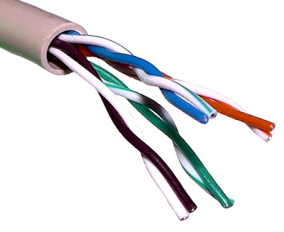
Unshielded twisted-pair (UTP) cable is the most common networking media. Unshielded twisted-pair (UTP) consists of four pairs of thin, copper wires covered in color-coded plastic insulation that are twisted together. The wire pairs are then covered with a plastic outer jacket. UTP cables are of small diameter and it doesn’t need grounding.  Since there is no shielding for UTP cabling, it relies only on the cancellation to avoid noise. 
Colors used for Twisted Pair wires are Orange, Orange-White, Blue, Blue-White, Green, Green-White, Brown and Brown-White. Following image shows a dissected Unshielded Twisted Pair cable.


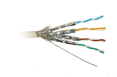
Shielded twisted pair is a special kind of copper telephone wiring used in some business installations. An outer covering or shield is added to the ordinary twisted pair telephone wires; the shield functions as a ground.


When talking about cable pinouts we often get questions as to the difference in Straight-through, Crossover, and Rollover wiring of cables and the intended use for each type of cable. These terms are referring to the way the cables are wired (which pin on one end is connected to which pin on the other end).

Straight-through Wired Cable

Straight-Through refers to cables that have the pin assignments on each end of the cable. In other words Pin 1 connector A goes to Pin 1 on connector B, Pin 2 to Pin 2 ect. Straight-Through wired cables are most commonly used to connect a host to client. When we talk about cat5e patch cables, the Straight-Through wired cat5e patch cable is used to connect computers, printers and other network client devices to the router switch or hub (the host device in this instance).


Crossover cable

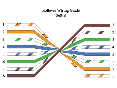
Crossover wired cables (commonly called crossover cables) are very much like Straight-Through cables with the exception that TX and RX lines are crossed (they are at oposite positions on either end of the cable. Using the 568-B standard as an example below you will see that Pin 1 on connector A goes to Pin 3 on connector B. Pin 2 on connector A goes to Pin 6 on connector B ect. Crossover cables are most commonly used to connect two hosts directly. Examples would be connecting a computer directly to another computer, connecting a switch directly to another switch, or connecting a router to a router.Note: While in the past when connecting two host devices directly a crossover cable was required. Now days most devices have auto sensing technology that detects the cable and device and crosses pairs when needed.


Rollover cable


Rollover wired cables most commonly called rollover cables, have opposite Pin assignments on each end of the cable or in other words it is "rolled over". Pin 1 of connector A would be connected to Pin 8 of connector B. Pin 2 of connector A would be connected to Pin 7 of connector B and so on. Rollover cables, sometimes referred to as Yost cables are most commonly used to connect to a devices console port to make programming changes to the device. Unlike crossover and straight-wired cables, rollover cables are not intended to carry data but instead create an interface with the device.

Fiber-Optic cable


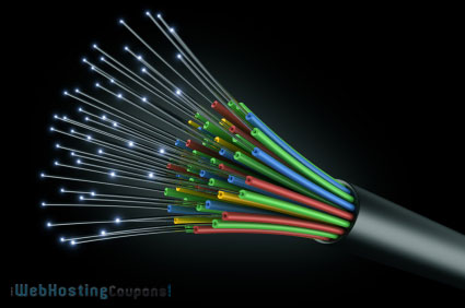
Optical Fiber cables use optical fibers that carry digital data signals in the form of modulated pulses of light. An optical fiber consists of an extremely thin cylinder of glass, called the core, surrounded by a concentric layer of glass, known as the cladding. There are two fibers per cable—one to transmit and one to receive. The core also can be an optical-quality clear plastic, and the cladding can be made up of gel that reflects signals back into the fiber to reduce signal loss.

There are two types of fiber optic cable: Single Mode Fibre (SMF) and Multi Mode Fibre (MMF).
1. Single Mode Fibre (SMF) uses a single ray of light to carry transmission over long distances.
2. Multi Mode Fibre (MMF) uses multiple rays of light simultaneously with each ray of light running at a different reflection angle to carry the transmission over short distances.


Wireless Technologies

802.11, 802.11b, 802.11b. 802.1g, 802.11n are a few of the of the wireless standards collectively known as WiFi technologies.

802.11

In 1997, the Institute of Electrical and Electronics Engineers (IEEE) created the first WLAN standard. They called it 802.11 after the name of the group formed to oversee its development. Unfortunately, 802.11 only supported a maximum network bandwidth of 2Mbps - too slow for most applications.

802.11b

IEEE expanded on the original 802.11 standard in July 1999, creating the 802.11bspecification. 802.11b supports bandwidth up to 11 Mbps, comparable to traditional Ethernet.

802.11b uses the same unregulated radio signaling frequency (2.4 GHz) as the original 802.11 standard. Vendors often prefer using these frequencies to lower their production costs. Being unregulated, 802.11b gear can incur interference from microwave ovens,cordless phones, and other appliances using the same 2.4 GHz range. However, by installing 802.11b gear a reasonable distance from other appliances, interference can easily be avoided.
  • Pros of 802.11b - lowest cost; signal range is good and not easily obstructed
  • Cons of 802.11b - slowest maximum speed; home appliances may interfere on the unregulated frequency band

802.11g

In 2002 and 2003, WLAN products supporting a newer standard called 802.11g emerged on the market. 802.11g attempts to combine the best of both 802.11a and 802.11b. 802.11g supports bandwidth up to 54 Mbps, and it uses the 2.4 Ghz frequency for greater range. 802.11g is backwards compatible with 802.11b, meaning that 802.11g access points will work with 802.11b wireless network adapters and vice versa.
  • Pros of 802.11g - fast maximum speed; signal range is good and not easily obstructed
  • Cons of 802.11g - costs more than 802.11b; appliances may interfere on the unregulated signal frequency

802.11n

802.11n (also sometimes known as "Wireless N") was designed to improve on 802.11g in the amount of bandwidth supported by utilizing multiple wireless signals and antennas (called MIMO technology) instead of one. Industry standards groups ratified 802.11n in 2009 with specifications providing for up to 300 Mbps of network bandwidth. 802.11n also offers somewhat better range over earlier Wi-Fi standards due to its increased signal intensity, and it is backward-compatible with 802.11b/g gear.
  • Pros of 802.11n - fastest maximum speed and best signal range; more resistant to signal interference from outside sources
  • Cons of 802.11n - standard is not yet finalized; costs more than 802.11g; the use of multiple signals may greatly interfere with nearby 802.11b/g based networks.


Referrences:
  • http://www.omnisecu.com/basic-networking/common-network-cable-types.php
  • http://searchnetworking.techtarget.com/definition/shielded-twisted-pair
  • http://compnetworking.about.com/cs/wireless80211/a/aa80211standard.htm
  • http://www.webopedia.com/TERM/8/802_11.html
Computer Network - OSI vs TCP/IP

The Open System Interconnect (OSI) Model


Layer 7— The application layer: This is the layer at which communication partners are identified, quality of service is identified, user authentication and privacy are considered, and any constraints on data syntax are identified. (This layer is not the application itself, although some applications may perform application layer functions). It represents the services that directly support applications such as software for file transfers, database access, email, and network games.

Layer 6—The presentation layer: This is a layer, usually part of an operating system, that converts incoming and outgoing data from one presentation format to another (for example, from a text stream into a popup window with the newly arrived text). This layer also manages security issues by providing services such as data encryption and compression. It’s sometimes called the syntax layer.

Layer 5—The session layer: This layer allows applications on different computers to establish, use, and end a session/connection. This layer establishes dialog control between the two computers in a session, regulating which side transmits, and when and how long it transmits.

Layer 4—The transport layer: This layer handles error recognition and recovery, manages the end-to-end control (for example, determining whether all packets have arrived) and error-checking. It ensures complete data transfer.

Layer 3—The network layer: This layer handles the routing of the data, addresses messages and translates logical addresses and names into physical addresses. It also determines the route from the source to the destination computer and manages traffic problems (flow control), such as switching, routing, and controlling the congestion of data packets.

Layer 2—The data-link layer: This layer package raw bit from the Physical layer into frames (logical, structures packets for data). It is responsible for transferring frames from one computer to another, without errors. After sending a frame, it waits for an acknowledgment from the receiving computer.

Layer 1—The physical layer: This layer transmits bits from one computer to another and regulates the transmission of a stream of bits over a physical medium. This layer defines how the cable is attached to the network adapter and what transmission technique is used to send data over the cable.


Protocol


TCP/IP Model


1. Application layer

This is the top layer of TCP/IP protocol suite. This layer includes applications or processes that use transport layer protocols to deliver the data to destination computers.  Some of the popular application layer protocols are :
  • HTTP (Hypertext transfer protocol)
  • FTP (File transfer protocol)
  • SMTP (Simple mail transfer protocol)
  • SNMP (Simple network management protocol) etc

2. Transport Layer

This layer provides backbone to data flow between two hosts. This layer receives data from the application layer above it. There are many protocols that work at this layer but the two most commonly used protocols at transport layer are TCP and UDP.

3. Network Layer

This layer is also known as Internet layer. The main purpose of this layer is to organize or handle the movement of data on network. By movement of data, we generally mean routing of data over the network. The main protocol used at this layer is IP. While ICMP(used by popular ‘ping’ command) and IGMP are also used at this layer.

4. Data Link Layer

This layer is also known as network interface layer. This layer normally consists of device drivers in the OS and the network interface card attached to the system. Both the device drivers and the network interface card take care of the communication details with the media being used to transfer the data over the network. In most of the cases, this media is in the form of cables. Some of the famous protocols that are used at this layer include ARP(Address resolution protocol), PPP(Point to point protocol) etc.

Comparison of OSI Reference Model and TCP/IP Reference Model

Following are some major differences between OSI Reference Model and TCP/IP Reference Model, with diagrammatic comparison below.
OSI(Open System Interconnection)TCP/IP(Transmission Control Protocol / Internet Protocol)
1. OSI provides layer functioning and also defines functions of all the layers.1. TCP/IP model is more based on protocols and protocols are not flexible with other layers.
2. In OSI model the transport layer guarantees the delivery of packets2. In TCP/IP model the transport layer does not guarantees delivery of packets.
3. Follows horizontal approach3. Follows vertical approach.
4. OSI model has a separate presentation layer4. TCP/IP does not have a separate presentation layer
5. OSI is a general model.5. TCP/IP model cannot be used in any other application.
6. Network layer of OSI model provide both connection oriented and connectionless service.6. The Network layer in TCP/IP model provides connectionless service.
7. OSI model has a problem of fitting the protocols in the model7. TCP/IP model does not fit any protocol
8. Protocols are hidden in OSI model and are easily replaced as the technology changes.8. In TCP/IP replacing protocol is not easy.
9. OSI model defines services, interfaces and protocols very clearly and makes clear distinction between them.9. In TCP/IP it is not clearly separated its services, interfaces and protocols.
10. It has 7 layers10. It has 4 layers


Referrences:


Monday, April 18, 2016

WDP - Foodelicious Bakeshop

I Car For You

FOODELICIOUS BAKESHOP!

Order Form


Shopping Address
Name:
Address
Email Address:
District:
Contact Number:
Delivery: Delivery Pick Up

Pastries To Order

Item Quantity Price
Cookies
Cupcakes

WDP - I Car For You

I Car For You

I CAR FOR YOU!

Registration Form
Username: Password
Email Address:
Contact Number:
Car:
Color: Red Blue Green Black Silver
Inquirie: Inquirie Test Drive Pick Up
Comment

Sunday, April 17, 2016

Module 2 Part 2 Exercise 18-4-2016

Computer Network

  • LAN
LAN stands for Local Area Network, is a group of computers which belongs to the same organisation, and are linked within a small geographic area using a network, and often the same technology - usually ethernet.
  • WAN
WAN (Wide Area Network) connects multiple LANs to one another over great geographical distances any network whose communications link cross metropolitan, regional, or national boundaries). The most well-known WAN is the Internet
  • MAN
MAN, Metropolitan Area Network connects multiple geographically nearby LANs to one another (usually over an area of up to dozen kilometers) at high speeds. In this sense, MAN connects two remote nodes, making them able to communicate as if they were part of the same local area network. Simply, MAN covers an area larger than LAN but smaller than that of WAN e.g. city. Best example of MAN is the cable television network available in many cities.
  • SAN
 SAN stands for Storage Area Network, System Area Network, Server Area Network or Small Area Network. Storage Area Network connects servers to data storage devices through a technology like Fibre Channel
  • VPN
Virtual Private Network, is a network that is constructed by using public wires - usually the internet - to connect to a private network (such a s a company's internal network).

Intranet vs Extranet

Intranet
An intranet is a set of Internet services (for example a web server) inside a local network, i.e. only accessible from workstations of a local network, or rather a set of well-defined networks that are invisible (or inaccessible) from the outside. It involves the use of Internet client-server standards (using TCP/IP) protocols such as, for example, the use of Web browsers (HTTP protocol-based client) and Web servers (HTTP protocol), to create an information system inside of an organization or enterprise.

Extranet
An extranet is an extension of the information system of the company to its partners located outside of the network.

Access to the extranet must be secured to the extent that the same provides access to the information system for persons located outside of the enterprise.


Intranet/extranet system

Bandwidth

When referring to a data connection, bandwidth or communication speed is the total maximum transfer rate of a network cable or device.

Networking Models

Network model defines a set of network layers and how they interect. There are several different network models mainly:

OSI vs TCP/IP

  • TCP/IP
This model is sometimes called the DOD model since it was designed for the department of defense It is also called the internet model because TCP/IP is the protocol used on the internet.

  • OSI
The International Standards Organization (ISO) has defined a standard called the Open Systems Interconnection (OSI) reference model. This is a seven layer architecture listed in the next section.


Reference:
  • http://ccm.net/contents/266-types-of-networks#lan
  • http://www.enggpedia.com/computer-engineering-encyclopedia/dictionary/computer-networks/1620-network-types-types-of-networks-examples-a-definitions
  • http://www.webopedia.com/TERM/V/VPN.html
  • http://ccm.net/contents/219-intranet-and-extranet
  • http://www.computerhope.com/jargon/b/bandwidt.htm
  • http://www.comptechdoc.org/independent/networking/protocol/protmodels.html

Wednesday, April 13, 2016

CN – Lab Exercise 2

Step 1 Establish and verify connectivity to the Internet
This ensures the computer has an IP address.


Step 2 Access the command prompt
Use the Start menu to open the Command Prompt window. Press Start, type Run then type cmd which stands as Command Prompt


Step 3 ping the IP address of another computer
In the window, type ping, a space, and the IP address of a computer recorded in the previous lab.


Ping uses the ICMP echo request and echo reply feature to test physical connectivity. Since ping reports on four attempts, it gives an indication of the reliability of the connection. Look over the results and verify that the ping was successful. Is the ping successful? Yes.
If not, perform appropriate troubleshooting. 
If a second networked computer is available, try to ping the IP address of the second machine.
Note the results.


Step 4 ping the IP address of the default gateway
Try to ping the IP address of the default gateway if one was listed in the last exercise. If the ping is successful, it means there is physical connectivity to the router on the local network and probably the rest of the world.


Step 5 ping the IP address of a DHCP or DNS servers
Try to ping the IP address of any DHCP and/or DNS servers listed in the last exercise.

If this works for both server and they are not in the network, what does this indicate?
The 2 are not in the same network but have the same DNS Server.

Was the ping successful? Yes.
If not, perform appropriate troubleshooting.


Step 6 ping the Loopback IP address of this computer
Type the following command: ping 127.0.0.1 
The 127.0.0.0 network is reserved for loopback testing. If the ping is successful, then TCP/IP is  properly installed and functioning on this computer.
Was the ping successful? Yes

If not, perform appropriate troubleshooting.


Step 7 ping the hostname of another computer

Try to ping the hostname of the computer that was recorded in the previous lab. 

If the ping is successful, it means the computer was able to resolve the host name to an IP address. Without name resolution, the ping would have failed because TCP/IP only understands valid IP addresses, not names.
If the ping was successful, it means that connectivity and discovery of IP addresses can be done with only a hostname. In fact, this is how many early networks communicated. If successful, then ping a hostname also shows that there is probably a WINS server working on the network. WINS servers or a local “lmhosts” file resolve computer host names to IP addresses. If the ping fails, then chances are there is no NetBIOS name to IP addresses resolution running.

Step 8 ping the Google web site
Type the following command: ping www.google.com


The first output line shows the Fully Qualified Domain Name (FQDN) followed by the IP address. A
Domain Name Service (DNS) server somewhere in the network was able to resolve the name to an IP address. DNS servers resolve domain names, not hostnames, to IP addresses. 

Without this name resolution, the ping would have failed because TCP/IP only understands valid IP addresses. It would not be possible to use the web browser without this name resolution.

With DNS, connectivity to computers on the Internet can be verified using a familiar web address, or domain name, without having to know the actual IP address. If the nearest DNS server does not know the IP address, the server asks a DNS server higher in the Internet structure. 

Step 9 ping the Microsoft web site
Type the following command: ping www.microsoft.com


Notice that the DNS server was able to resolve the name to an IP address, but there is no response.
Some Microsoft routers are configured to ignore ping requests. This is a frequently implemented security measure.
ping some other domain names and record the results. For example, ping www.msn.de

Ping www.facebook.com

ping www.tumblr.com

ping www.amazon.com

Step 10 Trace the route to the Yahoo web site
Type tracert www.yahoo.com and press Enter.

Tracert is TCP/IP abbreviation for trace route. The preceding figure shows the successful result when running tracert.
Each router represents a point where one network connects to another network and the packet was forwarded through.

Step 11 Trace other IP addresses or domain names
Try tracert on other domain names or IP addresses and record the results. An example is
tracert www.msn.de. 


tracert www.Amazon.com
tracert  www.yahoo.com

Step 12 Trace a local host name or IP address
Try using the tracert command with a local host name or IP address. It should not take long because the trace does not pass through any routers


Reflection 

If the above steps are successful and ping or tracert can verify connectivity with an Internet Web site, what does this indicate about the computer configuration and about routers between the computer and the web site? What, if anything, is the default gateway doing?

As shown, all ping and tracert was successful,and this proves that the IP Configurations are correct and then cable are properly connected to enable internet access. Ping is used to ensure proper internet connection between a web server and a computer, where the DNS configuration need to establish a successfull connection. Tracert is used to indicate the path that packets take from a computer to the internet - when accessing a website. With tracert, administrators can also monitor any problems within a network from a router that are not functioning properly .The purpose of a default gateway is to help local networks to connect to the internet.

References:
http://hnda-farah.blogspot.com/2016/04/cn-lab-exercise-2.html (for Reflection)

Tuesday, April 12, 2016

WDP Ex4 - Tables Are Complicated

Table Are Complicated
Tables Are Complicated
Mohammadbishr Hafiy
22 13 November 1993
HafiyXXX@gmail.com +673 XXXXXXX
HND Class A
A male Scorpio.

WDP Ex3 - Tables and Span

Table Time
Name Age
Khairun 19
Zura 19
Hafiy 17

Famous Monster by Birth Year
Famous Monsters Birth Year
King Kong 1993
Dracula 1897
Bride of Frankenstein 1935

Divide and Conquer

Spantastic

This text is black, except for the word red!

My favourite font is Impact!